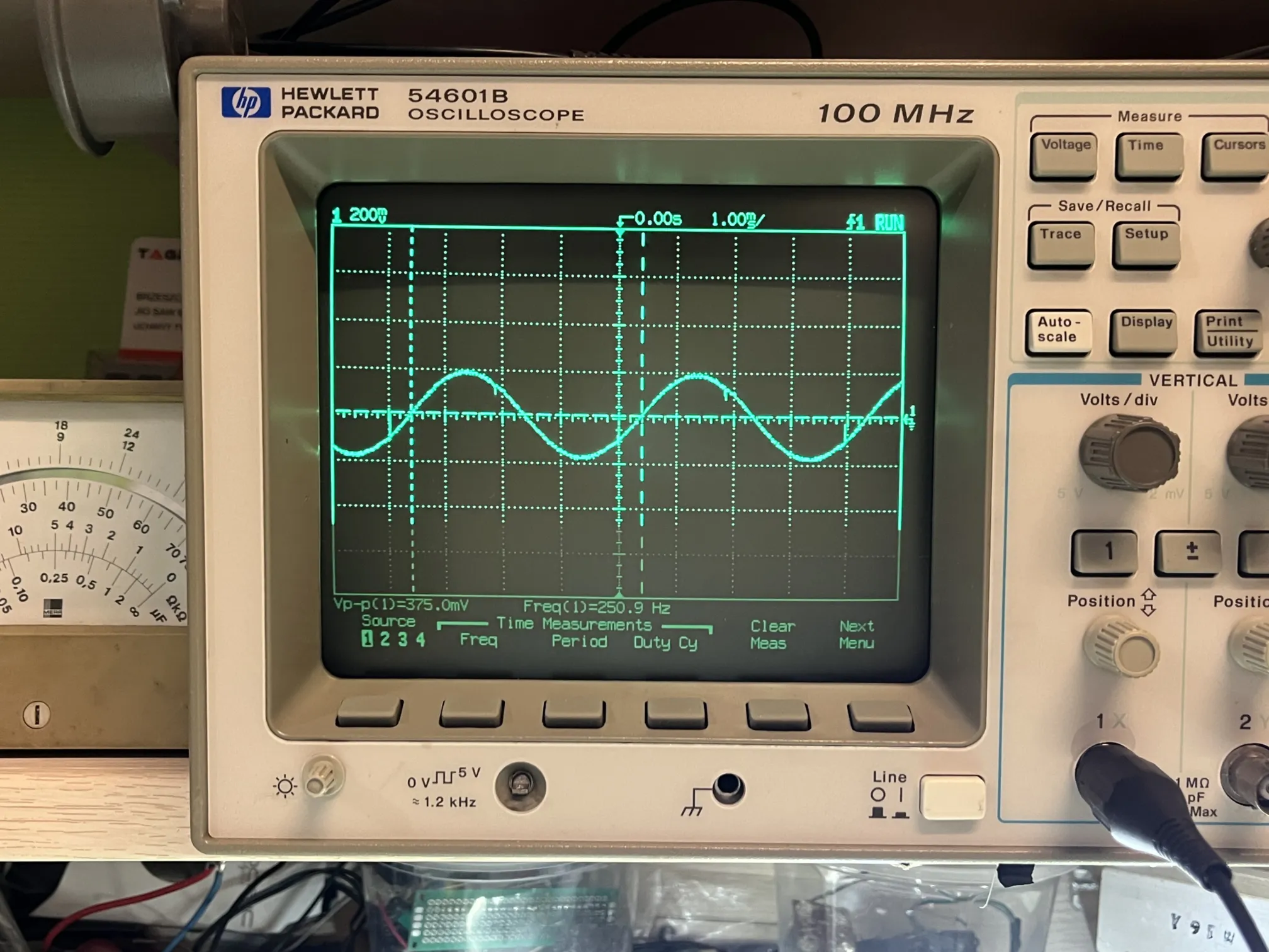
old bitch
i already have an oscilloscope. a hantek 6022be that i bought a while ago, new. it's a 20MHz digital usb-ifaced oscilloscope. really bare — doesn't even have ac-coupling. it's some unwanted child between a regular, more advanced oscilloscope, and a logic analyzer. and the software isn't very good. the input voltages are very limited and go down with V/div settings. just not a good purchase at all. it did carry me for a long time, and will probably still be used, because i can record its output to computer memory.
recently i've been hitting some walls while attempting to hack a jieli chip. it uses the usb to communicate with a my programmer. with the 20MHz scope i couldn't determine whether the signal quality was proper: because of limited bandwith, the differential signals often didn't match up, and i was left wondering what the failure mode is, and whose fault the failure is!!! around that time i started looking around for some other instruments. carrying a laptop to use the oscilloscope was getting annoying. i really wanted one of those old tek or hp scopes. they're just so beautiful with their vibrant, phosphor green crt displays. and after scouting for a while, i found an offer. hp54602b 100MHz 4-channel scope, with a probe, and an ieee 1284 iface module included; all for 500zł. a visible issue is a snapped encoder knob cap, and the first channel is broken, as described by the seller and detailed with photos.
i managed to hag the price down to 425zł, touching upon the dead channel. the failure looked very... capacitive. like some sort of high-pass filter has formed. this was actually a big push for me, because it meant to me that the issue is probably close to the input, and the digital side is still working, since the signal was still recognizable. i decided that this could actually be a repair worth tackling, so i paid up and waited for the package.
guts & blood
the scope arrived in a state worse than anticipated. one of the feet was smashed in. there was a horrible thermal paste-like substance slathered all over the insides. someone took a few bites out of the front panel plastics, too. apart from lots of regular usage scars, the shell also bears some number scratched in, right next to the word "x-ray". very, very interesting. i removed everything that needed removing and got to work. i cleaned most of the internals up, including that terrible gray goo i mentioned. one thing that immediately caught my eye: the attenuator shields are designed very well, and require no desoldering. the legs are bent in such a way to allow lifting of the shield easily, and the ground connection is achieved by pressure onto a large strip of soldered ground pad, all with a single screw.
i downloaded the service manual from the internet. there were no circuit schematics. i might be fucked. at least they showed how to get the front panel off, i would not've found the two plastic clips by myself. i started by checking out the power supplies and their ripple. i actually measured the ripple using the oscilloscope itself, which while cool, left me wondering whether this method would actually be accurate due to common-mode noise. but since everything other than one channel worked, i ignored potential power supply issues and went closer to the obvious. i started probing around channels 1 & 2, comparing the values of passives, and semiconductor voltage drops between the two. channel 2 was my control, channel 1 was the patient. one thing that immediately stood out to me was the coil resistance on one of the relays (i later learned that this is the voltage division relay). channel 1 showed around 30Ω on the coil, while both channel 2 and the datasheet show 185Ω. this was a big clue, and at the same time a bit of a red herring, as i'll explain later.
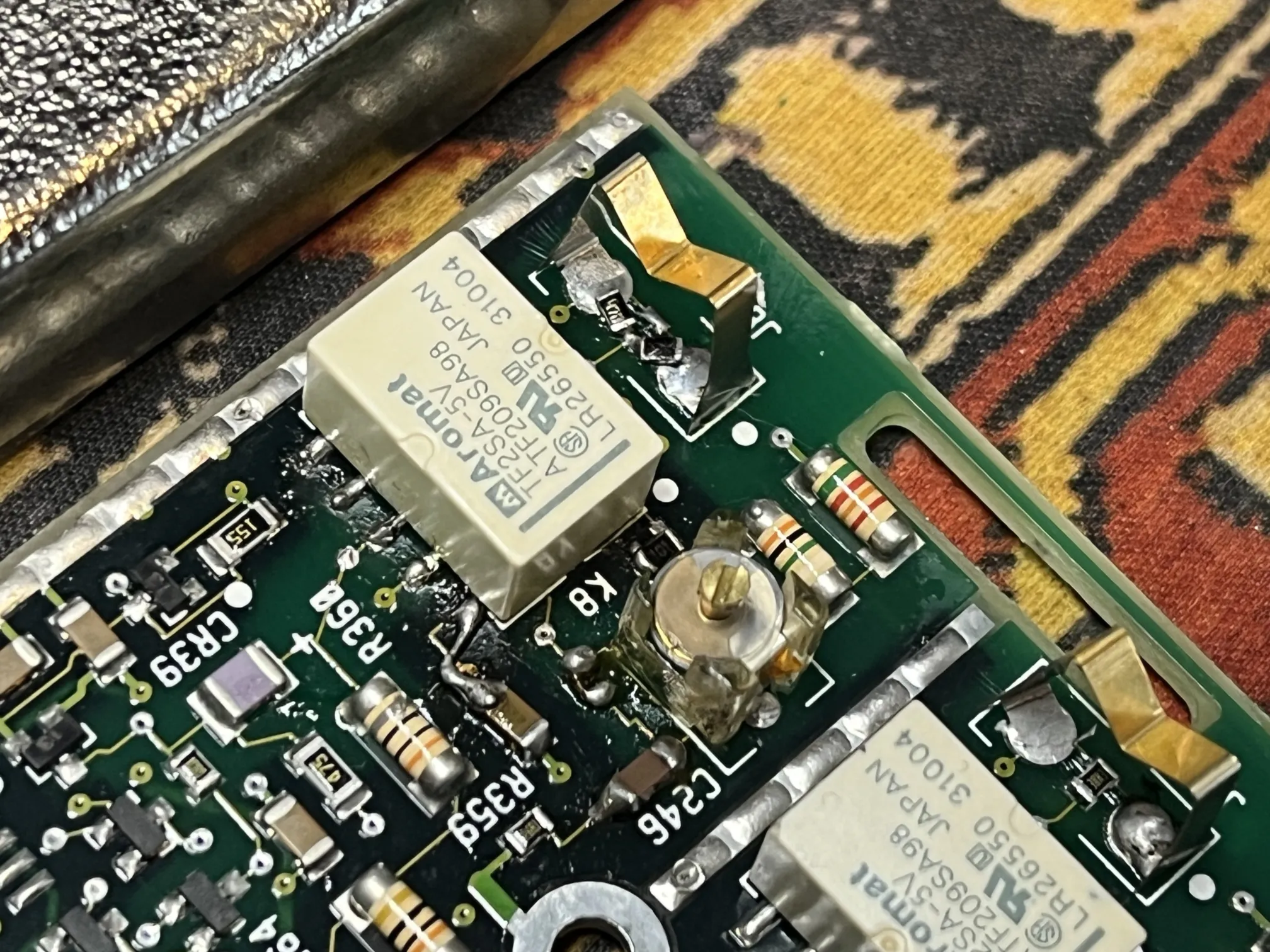
i immediately suspected the capacitor connected across one of the coil's legs, and ground. a resistance reading showed an 8Ω short. i took it off just to see a healthy 100nF cap, and the coil resistance increase to 55Ω. deceived by this increase, i started focusing on capacitors even more. i thought that maybe this was pulling some important voltage rail down and causing an amplifier to misbehave. actually, one of the worst possibilites was a broken at&t chip — probably some sort of amp, visible north of the attenuator circuit. i couldn't find one anywhere online. but voltage drops looked similar to the control, so i became less skeptical of it. eventually i found a dead 100 ohm resistor, next to the relay, reading «OL» on the dmm. upon replacing that passive with another one, which i found on a dead crt televisor's board, the coil resistance increased further to 70Ω. i also decided to check the coil itself, detaching one side of the relay pins from the board. i was too lazy to get the hot air station, and this way i ripped one of the pads. was easy to fix, though. the coil was good — resistance a bit on the high side, but good. after a lot of probing of the unpowered board, and multilayer pcb re-tracing nightmare, i arrived at a buffer inverter output, and a flip flop input, all connected to one side of the coil; both channels having respective outputs. i was very confused with these connections: why would these three be junctioned!? i looked around for faulty capacitors, and went to sleep.
making progress
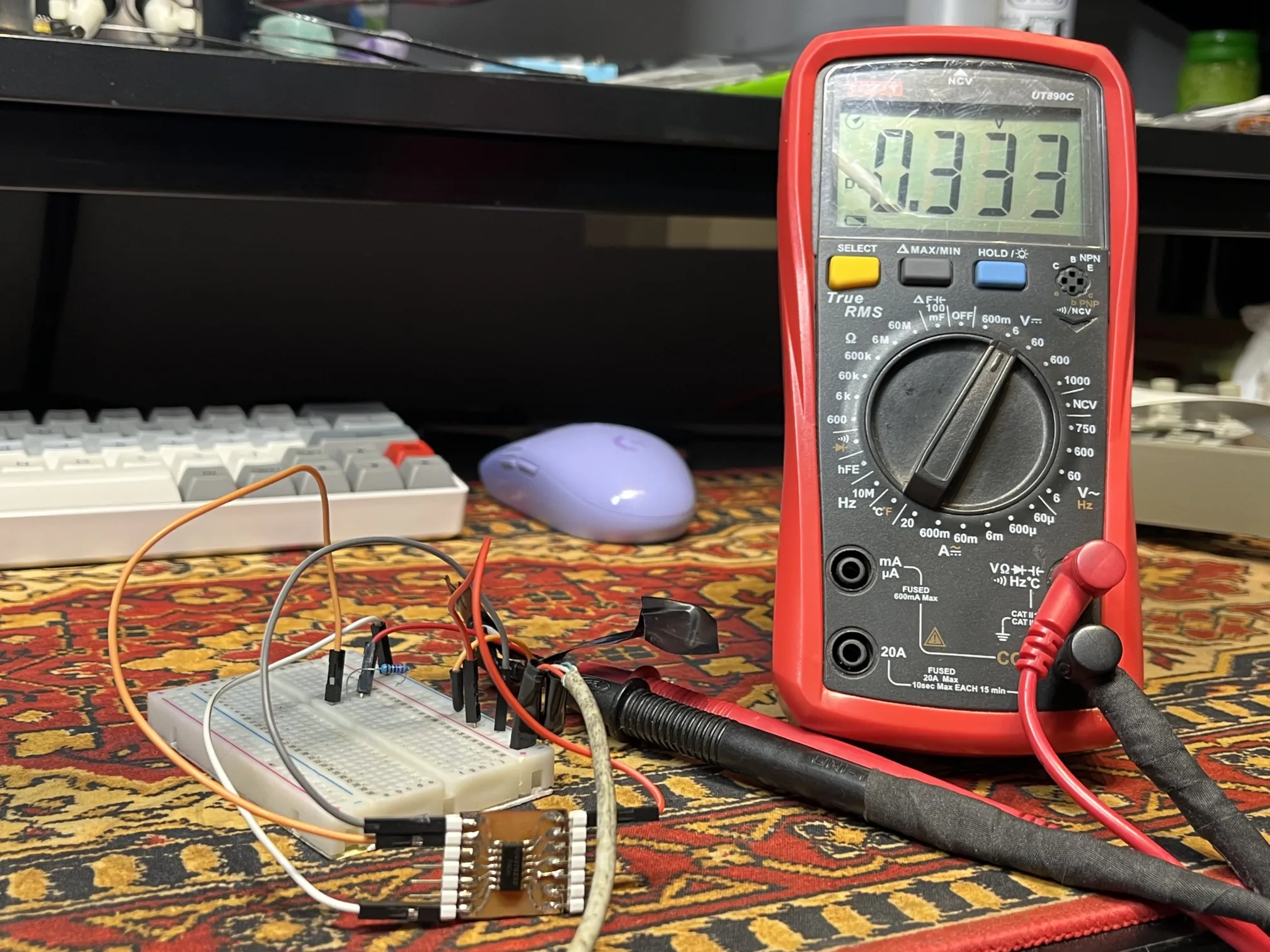
after sleeping on my newly acquired knowledge, i probed around more, and after a long time of doing that, i realized that the datasheet i pulled was for another flip-flop, and the pins i saw connected were actually outputs. i also found the schematics for another oscilloscope from the same series. they were terrible scans, but had just enough detail to make out what i needed. the attenuator sections were identical to mine, and the connections did indeed go to the ICs that i found. that's when it struck me. some ic is fucked. i took the inverter off: short gone. that's nice, but still doesn't solve my issue. even with the coil powered (default position), the signal experienced the "capacitive" issue. so while i was happy to find one of the faults, the big problem was still present. that's why this was a bit of a red herring. i confirmed that the single "channel" of this IC is in fact damaged with a simple test circuit. i didn't have this 7406 ic, so i just reattached it, and went looking for the other fault.
SIKE!!!
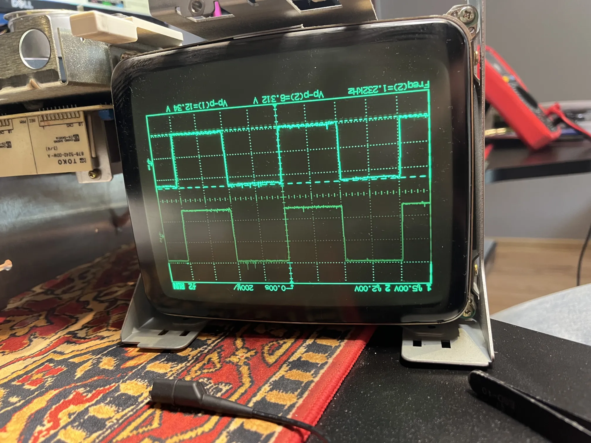
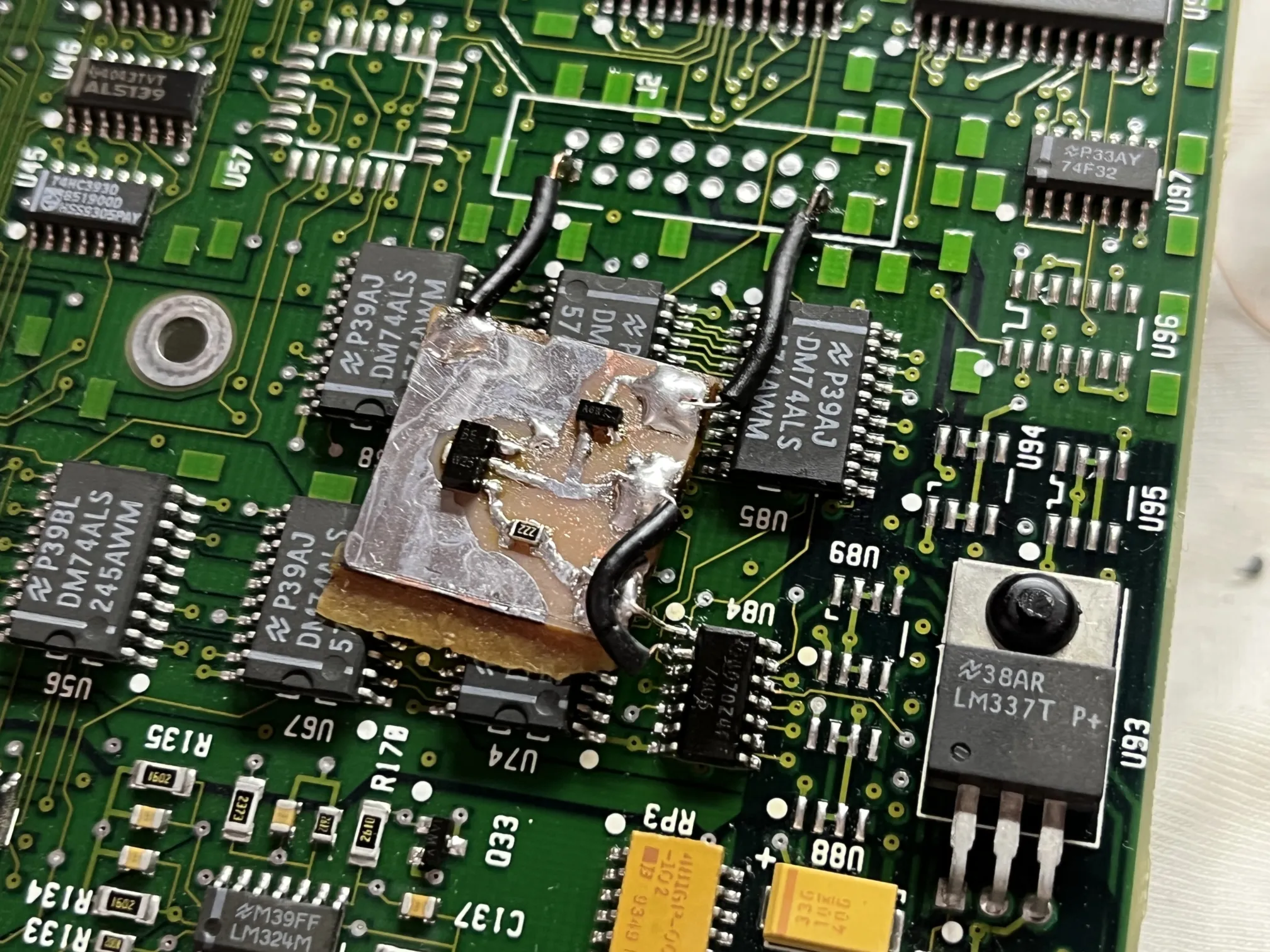
i made my own inverter! who needs an integrated circuit when you've got discrete components?? i looked at the internal circuit schematic of the 7406, and after grasping how it works (somewhat), i trashed their design and decided to use a single tranny. this isn't some fast signal that requires an electronic adept's brain for design: it's switching a damn mechanical relay, it'll be fine. i drew up a circuit, picked out some components from the trash, drew the pcb, and etched it. my version also has a flyback diode to protect the circuit. i tested it out on a 12v relay, worked without trouble. it should serve well — the target relay's coil is rated for just 5v.
i took the 7406 off again, bent input 1 and output 1's legs, allowing me to solder my inverter to the pads. i found some convenient gnd and 5v outputs on an unpopulated connector footprint. the 5v input is actually only needed for the flyback diode. this works because the inverter is an open-collector circuit, and the other side of the coil is connected to the 5v rail. this means that placing a diode with the cathode connected to 5v, and the anode to my collector, effectively puts it in parallel to the coil.
back 2gether
before even starting the repair, i've already cleaned out all the grime, goo, and tape residue, and didn't tell you about it; what a horrible person i am. well, the. i also glued that broken leg back in with two-part epoxy. i tested both of the inputs, and they read identically.
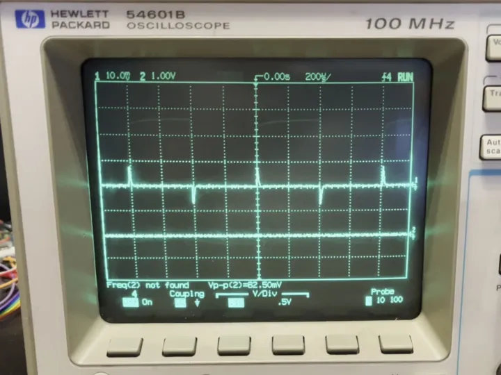
i now have a fully working 100MHz 4-channel scope... or do i????? after putting it together, i noticed that channels 3 and 4, when set to 0.1V/div, float above 0V and show weird charge-up behavior with this "bias". this time the problem affects two channels at the same time, and only on the low voltage division setting, which makes for interesting diagnonsis speculations, but i've ultimately decided that i'm fine with the current state of the instrument, and ignored that fault. the other division setting – 0.5V/div – barely fits a 5V signal on screen anyway (if it even does, i don't remember); i don't think i have any use for 0.1V/div.
one last mystery remaining is what even caused the damage? the resistors looked fine, except for a little black dot on the 100Ω resistor. maybe the «x-ray» writing has something to do with the damage. i'm not sure how components would fail under tens of kilovolts.
